On this page
- What are the core metal additive manufacturing processes?
- What is laser powder bed fusion (LPBF)?
- What is electron beam melting (EBM)?
- What is directed energy deposition (DED)?
- What are the main material-specific challenges in metal AM?
- What are the main porosity types in metal AM?
- How does residual stress affect metal AM parts?
- How does anisotropy affect mechanical properties in metal AM?
- What separates metal AM prototyping from production?
- What post-processing routes unlock metal AM performance?
- Key takeaways
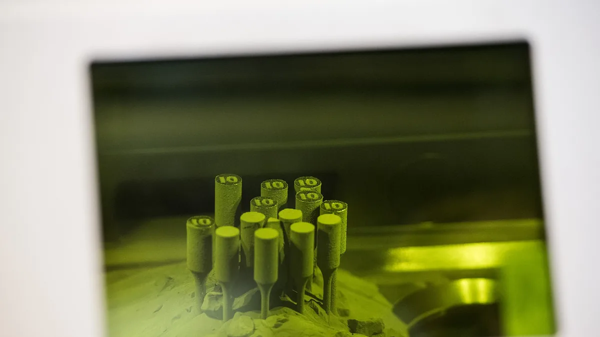

Metal additive manufacturing has moved beyond prototyping to become a viable process for production parts, but its adoption is not a simple substitution for casting or machining. The three main industrial processes, Laser Powder Bed Fusion (LPBF), Electron Beam Melting (EBM), and Directed Energy Deposition (DED), each produce a unique microstructure and defect profile. An engineer’s primary task is not just selecting a process but understanding how rapid solidification, thermal cycling, and process-induced defects like porosity and residual stress determine the final mechanical properties of the part.
What are the core metal additive manufacturing processes?#
Metal additive manufacturing has three core industrial processes: Laser Powder Bed Fusion (LPBF), Electron Beam Melting (EBM), and Directed Energy Deposition (DED). Each process builds parts by melting feedstock layer by layer. The energy source and feedstock delivery change the physics of melting, which affects the alloys that can be processed and the post-processing that must be specified.
LPBF uses a scanned laser on a powder bed, EBM uses an electron beam in a vacuum chamber, and DED feeds powder or wire into a moving energy source. These differences determine part size, resolution, material compatibility, and defect profile.
What is laser powder bed fusion (LPBF)?#
Laser Powder Bed Fusion (LPBF), also called selective laser melting (SLM), uses a high-power fiber laser scanned across a bed of fine metal powder, typically 15 to 100 microns in diameter. The laser fully melts the powder in a small melt pool, which rapidly solidifies as the beam moves on.
Build rates are relatively slow, which limits LPBF to smaller, highly complex parts such as conformally cooled tooling inserts, medical implants, and aerospace brackets. The fine laser spot size enables high-resolution features, but the rapid solidification can trap unwanted phases. For example, in LPBF of common aluminum alloys like AlSi10Mg, the solidification rate creates a fine cellular microstructure that provides higher as-built strength than the cast equivalent but also demands precise heat treatment to relieve residual stress.
What is electron beam melting (EBM)?#
Electron Beam Melting (EBM) uses a high-power electron beam instead of a laser to melt a metal powder bed in a vacuum chamber at elevated temperature. The powder bed is preheated and maintained at high temperatures, often exceeding 700 degrees Celsius for titanium alloys, which reduces the thermal gradient and residual stress.
The vacuum environment is a natural fit for reactive materials like titanium and nickel-based superalloys. The larger melt pool and pre-sintered powder bed produce a coarser microstructure and rougher surface finish compared with LPBF. EBM is typical for Ti-6Al-4V orthopedic implants and aerospace structural parts where stress relief and material integrity outweigh the need for fine surface detail.
What is directed energy deposition (DED)?#
Directed Energy Deposition (DED) builds metal by blowing powder or feeding wire through a nozzle into a focused energy beam, which can be a laser, electron beam, or electric arc. The nozzle moves over a substrate to add material layer by layer, and the process is less about high-resolution geometry than about adding material at a high rate.
Core applications for DED include part repair, adding features to existing forged blanks, and building larger near-net-shape structures. The process creates a larger melt pool with slower cooling rates, resulting in a more cast-like microstructure than LPBF. This makes DED suitable for alloys that are difficult to process in a powder bed but weldable in wire form, such as Invar or some high-strength steels.


What are the main material-specific challenges in metal AM?#
Material-specific challenges in metal additive manufacturing arise from each alloy’s response to rapid solidification, thermal cycling, and atmospheric contamination. Alloys such as AlSi10Mg and Ti-6Al-4V print readily, while high-strength wrought aluminum grades like 6061 and 7075 are prone to severe hot cracking unless modified.
- Aluminum Alloys: Casting grades like AlSi10Mg are printable. High-strength wrought grades like 6061 and 7075 suffer from severe hot cracking, also called solidification cracking, due to their wide freezing range. They are generally avoided unless specialized nanoparticle inoculants are added to the powder to promote fine equiaxed grain growth.
- Titanium Alloys: Ti-6Al-4V is the workhorse for both LPBF and EBM, but the interstitial pickup of oxygen and nitrogen from imperfect inert atmospheres is a constant concern. A brittle alpha-case layer can form on the surface, requiring chemical milling.
- Nickel Superalloys: Precipitation-hardenable alloys like Inconel 718 are printable but prone to strain-age cracking during post-build heat treatment if residual stress is not fully relieved first. Solid-solution-strengthened grades like Inconel 625 are easier to print.
- Steels: Tool steels (H13 and maraging steels) and stainless steels (316L and 17-4 PH) print reliably. Maraging steels are particularly effective because their low-carbon martensite is relatively soft as-built and easily machined, achieving high strength after a simple aging treatment.
What are the main porosity types in metal AM?#
Metal additive manufacturing produces three main porosity types: gas porosity, lack-of-fusion (LOF) porosity, and keyhole porosity. Gas pores are spherical and usually smaller than 50 microns, LOF defects are irregular and located between layers, and keyhole pores form at the base of the melt track from excessive energy density.
Distinguishing gas porosity from LOF is essential because their effect on mechanical properties, especially fatigue performance, is different.
| Porosity Type | Typical Cause | Shape | Typical Size (µm) | Typical Location | Critical Effect |
|---|---|---|---|---|---|
| Gas Porosity | Entrapped shielding gas, vaporized alloying elements, or powder particle porosity | Spherical | Less than 50 | Randomly distributed | Reduces fatigue limit moderately; can mostly be closed by hot isostatic pressing (HIP) |
| Lack-of-Fusion (LOF) | Insufficient energy density from low laser power, high scan speed, or thick powder layer | Irregular and elongated | Not specified | Often located between layers | Severe stress concentration; drastically reduces fatigue life; cannot always be fully healed by HIP |
| Keyhole Porosity | Excessive energy density causing vapor depression collapse | Roughly spherical | Not specified | At the base of the melt track | Acts as a crack initiator under cyclic loading |
For production parts, computed tomography (CT) scanning is becoming the nondestructive evaluation (NDE) standard for detecting critical LOF porosity. Ultrasonic testing may be sufficient for simple geometries with low distortion.
How does residual stress affect metal AM parts?#
Residual stress in metal additive manufacturing develops when a newly deposited hot layer is constrained by cooler, already-solidified material below it. As that new layer cools and contracts, it develops tensile stress, while the substrate enters compression to balance the force field. This stress can distort parts, cause cracking, and pull the part off the build plate.
The first line of defense is the build preparation strategy. Rotating the scan vector by a specific angle, usually 67 degrees, per layer breaks up the stress direction. Using a heated build plate reduces the thermal gradient. A thermal post-process is mandatory for structural parts. A stress-relief heat treatment cycle before the part is cut from the build plate is standard, followed in many cases by hot isostatic pressing (HIP) to simultaneously collapse internal defects and relieve residual stress completely. For an overview of the thermal cycles involved, see our guide on Steel Heat Treatment: Processes, Microstructures, and Properties.
How does anisotropy affect mechanical properties in metal AM?#
Anisotropy in metal additive manufacturing means that mechanical properties depend on build direction. A vertical Z-axis tensile coupon often shows lower ultimate tensile strength and lower elongation at break than a horizontal XY coupon from the same build, because columnar grains grow along the build direction.
A cast billet is isotropic when texture effects are ignored, but an AM part is a composite of thousands of individual weld tracks, producing both microstructural and mechanical anisotropy. Most grains tend to grow epitaxially along the build direction, or Z-axis, in the direction of the steepest thermal gradient, creating a columnar grain structure. Fatigue behavior is similarly orientation-dependent. Engineers cannot rely on data taken from XY coupons to qualify a load-bearing Z-axis component. A mechanical test protocol must account for the part’s orientation in the build chamber, explicitly sampling the critical stress direction. You can find the key definitions in our guide to Key Metallurgy Terms Every Engineer Should Know.


What separates metal AM prototyping from production?#
Metal additive manufacturing prototyping and production differ in process control and acceptance criteria. A prototype may use manually adjusted parameters on one machine and a single destructive cross-section for porosity. Production requires a frozen, statistically validated process chain with controlled powder quality, locked parameters, and defined nondestructive defect limits.
For a prototype, an engineer might manually tweak a few parameters on a single machine to get a part that fits a gauge and looks good on a bench. Porosity might be assessed with a single destructive cross-section. For production, the entire process chain must be frozen and statistically capable. This means using pre-qualified, recycled powder with a known chemical composition, a locked parameter file that has survived a design of experiments (DOE) to prove a robust process window, and a part-specific post-process routing that includes residual stress relief, hot isostatic pressing, and nondestructive testing. Acceptance criteria shift from no visible defects to a defined maximum defect size distribution as validated by CT scanning and an allowable fraction of porosity by area. The insight from a related process is instructive here; even in Powder Metallurgy: Process, Materials, and Advantages, the variance in compaction and sintering must be tightly controlled to match wrought properties, a challenge magnified in the highly non-equilibrium AM process.
What post-processing routes unlock metal AM performance?#
Post-processing routes for metal additive manufacturing include stress relief, hot isostatic pressing (HIP), surface finishing, and alloy-specific heat treatment. These steps are part of the material definition because as-built surfaces are rough and tensile data from polished test bars do not represent as-built parts.
As-built metal AM surfaces are rough and often act as a pre-populated field of crack-initiation sites. The post-processing sequence is part of the material definition.
- Stress Relief: Performed in a furnace with the parts still attached to the build plate to prevent distortion during cutoff.
- Hot Isostatic Pressing (HIP): Applies high pressure and temperature via an inert gas to collapse internal pores and full-density diffusion-bonding, transforming fatigue performance from a flaw-controlled state to a material strength-controlled state.
- Surface Finishing: This can include vibratory finishing, abrasive-flow machining for internal channels, or electrochemical polishing. The goal is to reduce surface roughness from Ra values of 20 to 30 microns to below 5 microns or to create a compressive residual stress layer via shot peening.
- Heat Treatment: This must be alloy-specific. For example, a solution anneal for a precipitation-hardenable stainless steel follows HIP to tailor the final strength and corrosion resistance.
Key takeaways#
Key takeaways for metal additive manufacturing are to match the process to the part, identify porosity correctly, require orientation-dependent tensile and fatigue test data, treat the post-processing chain as part of the material specification, and lock the full process, including powder recycling control, before production release.
- Match the process to the part critically: LPBF for high complexity, high resolution; EBM for low residual stress in titanium; DED for repair and oversized near-net structures.
- Identify porosity correctly: look for irregular lack-of-fusion defects, not just spherical gas pores, as these dictate whether HIP will be successful.
- Mandate orientation-dependent tensile and fatigue test data: using XY properties to design for Z-axis loads will lead to component failure.
- Treat the post-processing chain as a non-negotiable part of the material specification, not an optional extra.
- Lock the full process, including a controlled powder recycling protocol, before releasing a part for production, bridging the gap from a prototype demonstration to a qualified, reliable component.