On this page
- What are the three stages of fatigue failure?
- How do stress concentrations affect fatigue failure?
- How does surface finish affect fatigue life?
- How do residual stresses affect fatigue life?
- How does mean stress affect fatigue life?
- What design strategies prevent fatigue failure?
- How do manufacturing processes affect fatigue resistance?
- How are fatigue cracks detected and monitored?
- Key Takeaways
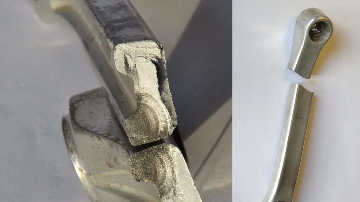

Fatigue failure is a progressive, localized damage process that occurs in metals subjected to cyclic loading, even when peak stresses remain well below the material’s tensile strength. It accounts for the majority of in-service mechanical failures and proceeds through three distinct stages: crack initiation, crack propagation, and final fracture. By understanding these mechanisms and the influence of stress concentrations, surface condition, and mean stress, engineers can design components with significantly improved fatigue resistance.
What are the three stages of fatigue failure?#
Fatigue failure in metals occurs in three sequential stages: crack initiation, crack propagation, and final fracture. Crack initiation begins at surface or subsurface defects under cyclic loading. Crack propagation advances the crack incrementally with each load cycle. Final fracture happens suddenly when the remaining cross-section can no longer carry the applied load. Each stage leaves characteristic marks on the fracture surface that aid in failure analysis.
Crack Initiation#
Crack initiation typically occurs at a free surface where cyclic slip is unconstrained. Under repeated loading, persistent slip bands form, creating intrusions and extrusions that act as micro-notches. These surface roughening features concentrate stress and eventually develop into a microcrack. Initiation can also occur at subsurface defects such as inclusions, porosity, or large second-phase particles, especially in high-strength steels where the matrix is more sensitive to stress concentrations. The number of cycles spent in initiation can be a large fraction of total life in high-cycle fatigue.
Crack Propagation#
Once a microcrack forms, it grows incrementally with each load cycle. Early growth (Stage I) occurs along crystallographic slip planes at roughly 45° to the applied stress axis. After a few grains, the crack transitions to Stage II growth, advancing perpendicular to the maximum principal tensile stress. This stage produces microscopic beach marks or striations, each corresponding to one or a few load cycles. The crack growth rate in Stage II is described by the Paris’ law, da/dN = C(ΔK)^m, where ΔK is the stress intensity factor range. The constants C and m are material dependent and are critical for damage-tolerant design.
Final Fracture#
When the remaining uncracked cross-section can no longer support the applied load, the component fractures suddenly. The final overload region may exhibit ductile dimples or brittle cleavage, depending on the material and loading rate. The relative size of the fatigue propagation zone and the final fracture zone helps analysts estimate the stress level at failure; a small fatigue zone with a large overload region suggests high nominal stress, while a large fatigue zone indicates lower stress.
How do stress concentrations affect fatigue failure?#
Stress concentrations at geometric discontinuities such as holes, fillets, grooves, and keyways are the primary initiation sites for fatigue cracks. These features raise local stress well above the nominal value, drastically reducing fatigue life. The severity is quantified by the stress concentration factor K_t and the fatigue notch factor K_f, which account for material notch sensitivity.
The theoretical stress concentration factor K_t is the ratio of the maximum local stress to the nominal stress, as derived from elasticity theory. However, not all materials exhibit the full theoretical reduction in fatigue strength. The fatigue notch factor K_f, defined as the ratio of the unnotched fatigue limit to the notched fatigue limit, is often lower than K_t because of local yielding and notch sensitivity. The relationship is given by the notch sensitivity index q = (K_f - 1)/(K_t - 1), where q ranges from 0 (no sensitivity) to 1 (full sensitivity). Cast irons, for example, have low notch sensitivity because of the stress-relieving effect of graphite flakes, while high-strength steels are highly notch sensitive.
A practical rule of thumb: a sharp 90-degree corner can reduce the fatigue strength of a steel shaft by 50% or more compared to a polished, unnotched specimen. Replacing a sharp shoulder with a generous radius can recover much of that loss.
How does surface finish affect fatigue life?#
Because most fatigue cracks initiate at the surface, the condition of that surface is a first-order variable. Surface roughness creates a multitude of micron-scale stress raisers that accelerate crack initiation. The surface finish factor C_s is used to derate the endurance limit of a polished laboratory specimen to account for production surface conditions. Typical values for steel are shown in the table below.
| Surface Condition | Approximate Surface Finish Factor C_s (Steel) |
|---|---|
| Polished (mirror) | 1.0 |
| Ground (fine) | 0.90 - 0.95 |
| Machined (turned) | 0.70 - 0.85 |
| Hot-rolled | 0.50 - 0.70 |
| As-forged | 0.40 - 0.55 |
| Corroded in tap water | 0.20 - 0.35 |
How do residual stresses affect fatigue life?#
Residual stresses in the surface layer of a metal component significantly influence fatigue life. Compressive residual stresses, introduced by processes like shot peening, case carburizing, or nitriding, lower the local mean stress and retard crack initiation and growth. Tensile residual stresses from grinding burns, abusive machining, or decarburization drastically reduce fatigue life.
In aluminum alloys, a machined surface with a light peening treatment can double the endurance limit compared to a coarse machined finish.


How does mean stress affect fatigue life?#
The mean stress around which a cyclic stress oscillates directly affects the allowable alternating stress for a given fatigue life. Tensile mean stresses reduce fatigue strength, while compressive mean stresses increase it. This relationship is captured by constant-life diagrams using criteria such as the modified Goodman relation, Soderberg criterion, and Gerber parabola.
The most widely used is the modified Goodman relation: σ_a / σ_e + σ_m / σ_uts = 1, where σ_e is the endurance limit under fully reversed loading (R = -1) and σ_uts is the ultimate tensile strength. The Soderberg criterion (using yield strength instead of UTS) is more conservative and often used for ductile materials. The Gerber parabola offers a less conservative fit for ductile steels. The load ratio R = σ_min/σ_max is a convenient way to characterize mean stress: R = -1 is fully reversed, R = 0 is zero-to-tension, and positive R values indicate a tensile mean stress.
For design, always consider the worst-case loading scenario. A rotating shaft with a constant bending moment experiences fully reversed stress (R = -1), while a preloaded bolt in a cyclic tension joint may see a high mean stress with a small alternating component. Compressive residual stresses introduced by surface treatments shift the effective mean stress in a favorable direction.
What design strategies prevent fatigue failure?#
Effective fatigue prevention starts with design decisions that minimize stress concentrations, specify beneficial surface treatments, and select appropriate materials. Key measures include using generous fillet radii, smoothing cross-section transitions, placing notches in low-stress areas, and introducing compressive residual stresses through shot peening or case hardening.
- Eliminate sharp corners: Use the largest possible fillet radius at every step or shoulder. A radius of at least 0.1 times the smaller diameter is a common starting point.
- Smooth transitions: Taper changes in cross-section gradually. Conical transitions and undercuts relieve stress flow.
- Place notches in low-stress regions: Position keyways, grooves, and holes away from peak bending or torsional stress locations.
- Specify surface treatments: Call out shot peening, rolling, or case hardening for critical surfaces, especially in parts that are machined or ground.
- Select materials with high notch toughness: In applications where stress concentrations are unavoidable, use alloys with higher ductility and fracture toughness.
- Avoid tensile residual stresses: Control heat treatment and machining to prevent decarburization and grinding burns. Specify stress-relief operations after welding or heavy machining.
- Use prestressing: Controlled overloading or autofrettage can introduce beneficial compressive residual stresses at bores or fillets.
- Consider corrosion protection: Corrosion pitting creates severe stress raisers. Apply coatings, platings, or use corrosion-resistant alloys if the environment is aggressive.
When a component cannot be redesigned, consider reducing the nominal stress by increasing section size or using a higher-strength material, but be aware that high-strength steels are more notch sensitive and demand better surface finish. For more on material selection, see How to Select the Right Aluminum Alloy for Your Project and Key Metallurgy Terms Every Engineer Should Know.
How do manufacturing processes affect fatigue resistance?#
Manufacturing processes can either preserve or degrade the inherent fatigue resistance of a metal component. Machining with dull tools or improper grinding can introduce surface damage and tensile residual stresses that promote crack initiation. Conversely, controlled processes like shot peening, carburizing, and nitriding improve fatigue life by imparting compressive residual stresses and hardening the surface.
Machining processes that leave a torn or smeared surface, such as aggressive turning or milling with dull tools, introduce surface damage and tensile residual stresses. Finish grinding with proper coolant and wheel dressing is essential for high-strength steels to avoid grinding burns that locally re-harden and crack the surface.
Shot peening is one of the most effective and controllable methods for improving fatigue life. The process bombards the surface with small spherical media, plastically deforming a thin layer and creating a balanced compressive residual stress field. Peening intensity, measured by Almen strip arc height, must be specified correctly: too low gives insufficient compression, too high can cause surface damage. Case hardening processes like carburizing, nitriding, and carbonitriding combine a hard, wear-resistant case with compressive residual stress, providing a double benefit. However, any subsequent grinding must be carefully controlled to avoid removing the compressed layer or introducing tensile stresses.
For welded structures, fatigue cracks often initiate at weld toes due to the combination of a geometric notch, tensile residual stress, and potential weld defects. Post-weld toe grinding, TIG dressing, or peening can improve fatigue performance. The Quality Inspection Checklist for Metal Parts covers practical checks for surface integrity.
How are fatigue cracks detected and monitored?#
Fatigue cracks can be detected before they reach critical size using nondestructive inspection methods. The choice of method depends on material, geometry, and accessibility. Common techniques include dye penetrant testing for surface cracks, magnetic particle inspection for ferromagnetic steels, eddy current testing for nonferrous alloys, and ultrasonic testing for volumetric inspection.
- Dye penetrant testing: Simple and low-cost for surface-breaking cracks in non-porous metals. Effective for field inspection of welds and machined parts.
- Magnetic particle inspection: More sensitive than dye penetrant for ferromagnetic steels, capable of revealing fine cracks at fillets and radii.
- Eddy current testing: Excellent for detecting small surface and near-surface cracks in nonferrous alloys and for inspecting fastener holes in aircraft structures.
- Ultrasonic testing: Used for volumetric inspection of thick sections and for sizing internal cracks, although it requires skilled operators.
Establish inspection intervals based on crack growth analysis or service experience. Focus on known hot spots: sharp corners, keyways, threads, weld toes, and areas of fretting. Record crack locations and sizes to support damage-tolerance assessments. For critical components, combine periodic inspection with a retirement-for-cause or safe-life philosophy. Understanding how to interpret material test data is essential; refer to How to Read a Tensile Test Report and Material Data Sheet for background on mechanical properties.
Key Takeaways#
- Fatigue failure occurs in three stages: crack initiation, crack propagation, and final overload fracture.
- Stress concentrations from geometric features are the most common crack initiation sites; use generous radii and smooth transitions to minimize K_t.
- Surface finish directly controls the endurance limit; specify polished, ground, or peened surfaces for highly stressed parts.
- Compressive residual stresses from shot peening or case hardening counteract tensile mean stresses and extend life.
- Mean tensile stress reduces allowable alternating stress; use Goodman or Soderberg diagrams for safe design limits.
- Good design, controlled manufacturing, and periodic nondestructive inspection form a practical triad for fatigue prevention.